
Practical science and engineering projects
15 Septembre 2016

In my region, like in many places nearby mountains, fishing for brown trout is one of the traditional outdoor activities. The local fishing style vary slightly depending on the topography of the rivers but natural bait fishing (using worms, natural flies, etc...) is one of the most common technique.
I, myself, have been practising this for many years now and have grown some educated opinion about the fishing tackle. Last year, I noticed that some of the most elementary fishing reel went up considerably in price. I am unsure of why that is but I thought it was then not worth the price the manufacturer was charging for what is wire a line tank. That's something very specific to the natural bait fishing technique (particularly in mountain rivers) and to a certain extend to fly fishing : the reel is hardly ever used to land a fish, it's simply a convenient line dispenser which should not harm the fishing action. We mostly ask it to give some line when pulling gently, not cause any slack when not asking for it, being immune to tangling and being capable of catching up with loose line quickly but without much tension on the line. The rest of the fishing action is directly down to your hands. Oh, and of course : it must be super light.
Knowing that there won't be much mechanical stress on that reel, and having identified some aspects that I disliked in my current reel, I then decided to design my own and print it at home.
My favourite reel : simple, light and left handed version
So first of all, I had to identify what I really wanted out of this reel. What instantly came out of my mind was :
That was basically it, I never wondered about the total weight other than carving out unrequired matter but this is part of the 3D design job anyway.
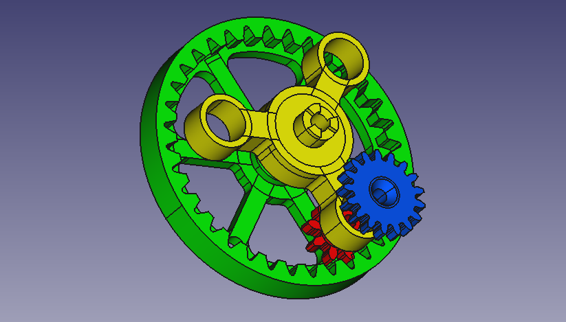
The first design element that I could identify was that, in order to achieve a high catch up rate in the small form factor I would certainly necessarily need to have a ring gear on the handle side. It was the only large gear that would not cause something to stick out of its envelope. On top of this, I soon found out that, having large gear was a must since the teeth definitely need to have a certain minimal size to work when 3D printed.
Lastly, I noticed that since the PLA I'm printing out of is somehow flexible, I would need to balance the stress and pressure on the different gears so I decided to go for an epicyclic gear with one ring gear linked to the handle and 3 planetary gear pairs. Note that on the picture taken from the 3D model, only one set of planetary gears is represented, the 2 other sets being identical and forming an equilateral triangle with the first one.
The next problem I had to solve was how to link that mechanism to the fixed base of the rod without having any fixed part exposed to the line (that's to avoid tangling again). I really wanted to avoid the handle/fixed base/reel order.
When you first think about it, it's not completely obvious but then I realized that I could have the handle/fixed planetary/reel stack with the link from the fixed base going through the reel's axis to hold the yellow part (planetary mount). This way, the reel could cover the whole mechanism just like shown on the pictures below.


The reel (in grey) covers the whole mechanism
In such configuration, the ring gear on the handle side is flush to the side of the reel and the risks of the line getting into the mechanism is very low.
What I did not mention so far is that I decided that all the rotary elements would be mounted on bearings. It sounds pretty obvious that we want minimal friction in that mechanism but it did add some constraints to the design since small sealed bearings are not very easy to find. I also paid a lot of attention to the price of the bearings since I really wanted to make an economical reel. In the end, I got my bearings from http://www.micro-bearing.fr which offers a nice selection of bearings for a very fair price. So I picked :
The three smaller ones are used for the planetaries and the two larger ones are for the handle and the reel. You can seen on the cut view that the green part and the yellow part have an axis sticking out to link to the next bearing. Also the reel has got a large tapered hole opened for the rod mount to be assembled on the outer side of it.
At that point, I had a reel with a minimal outside radius of 33mm and an epicyclic gear developing a 3.54:1 ratio (that's 35 teeth on the green ring gear linking to a 8 teeth red gear on one side and a 17 teeth blue gear on the other side which is linked to a 21 teeth sun). This design was then offering a minimum of 73.4cm per handle rotation which is well enough for me.
The mount linking the reel to the rod
So we have the reel, but despite what it sounds, designing it was not the longest in the process. As usual, the sum of the less central questions did more or less balance the central bit in allocated time.
What was remaining to identify was :
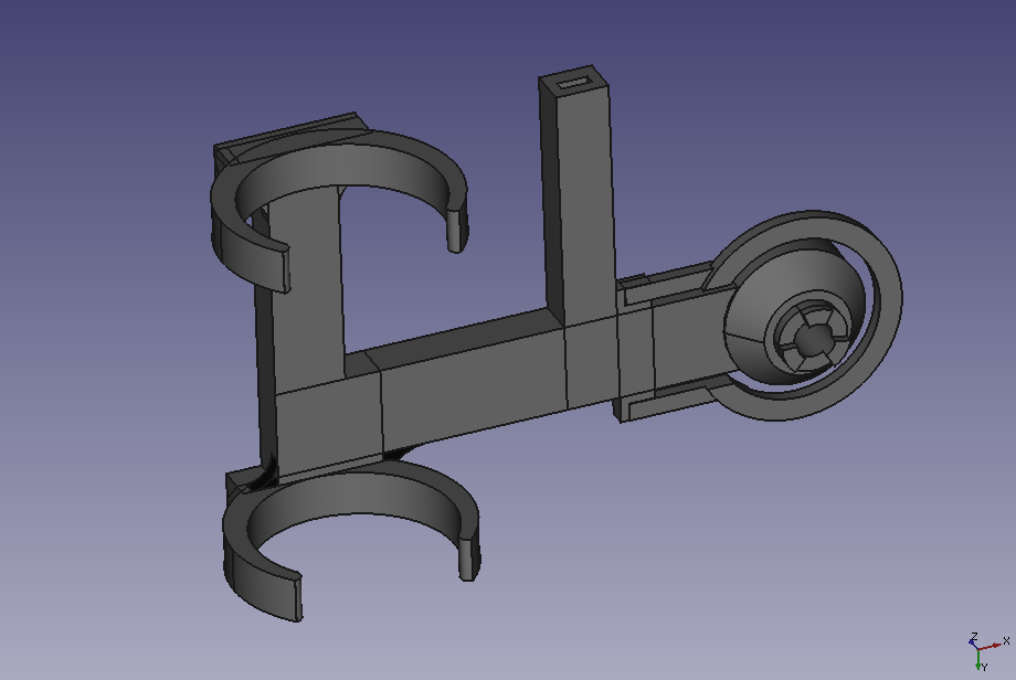
So the easiest one to answer was the first point. For any reason, I did not want to use the conventional reel mount which is simply a plate locked between two rings attached to the rod. The main reason was that it was complicating the design since the mount would not have printed in one go and I wanted this mount to be a strong part. So I thought that after all, the 3D printer is meant to allow for some custom design so I decided to make a mount for my rod specifically. I designed two clips which would nicely fit the diameter of the rod's handle and thought everyone could adjust the inner diameter to match their own rod's. That's when I realised that rod handle diameters are almost exactly the same on all my rods... So probably that design a slightly more universal than I thought. Hence I decided to stick to it.
You'll notice on the picture below that the mount connects to the yellow planetary mount through the reel's axis and the very connection is using three teeth to avoid free rotation. The last thing you'd want to see is the yellow part turning, this would then take the catch up ratio back to 1:1.

Left handed mount assembling to the reel
You might have noticed from the second picture in this post but I'm left handed. When looking for a reel, I'm very attentive to whether these are suitable for left handed people. So naturally, the mount I've been printing is for left handed people like me. But no panic, the whole design is suitable for right handed people as well, you simply have to mirror the mount and nothing else. I can even tell you that Cura offers the symmetry transform so no need to fiddle with the 3D model.
This being said, the next big deal was the brake.
While fishing, you want to focus on the fishing action, not on your tackle. That's why a bad brake will just cause immediate rejection. A bad brake is one that either does not let you set the exact tension at which the line can be pulled or one that is jerky as you pull (with important variations in tention) or one that is hard to reach and tweak when you need it (normally in emergency since the fish is pulling too hard).
This being said, how do you avoid these problems ? My answer to this question was to identify some basic principles to avoid this problems. So here they are :
Altogether and since I was constrained by the rest of the design, this led me to add that long little stripe that you could already see surrounding the reel connecting end. This is meant to be a spring that will press onto the reel's surface to give us the required friction.
Now I had to design a mechanism to press onto it and that was actually pretty straightforward as shown on the picture bellow.

The brake cover (blue) and knob (red)
The whole assembly is mounted around a central M3 threaded rod. Loose bits are rebored and the fixed ones are self-tapered (don't use a tap, it's ending up loose).
You might have noticed that below the blue cover, there's a cavity in the mount : this is where a M3 nut is placed to make the assembly solid independently of the brake position.
Now the icing on the cake : the line guide. Of course we want to limit the possibilities of the wire jumping out of the reel in an unordered fashion and on top of that, when you're pulling some line out, you want to feel the tension against a certain very smooth and resistant part : the line guide.
In this reel's design, the reel is very large and completely open so we don't really have to worry about the line curling, hence no need for a long tunnel like on my favourite reel. I picked a rod tip ring to act as a line guide, they are easy to find and are designed to resist intensive line friction. I decided to have that part mounted onto the mount on a little dedicated post. I moved that post around a couple of times to make sure I was setting the guide in a position where the line would enter the reel more or less always tangent to it (that's without making a silly angle to the ring). In fishing action, you take the line in your hand (right one for me) and pull it away from the rod to give more friction around that guide and feel the touches. At that point, the fishing technique is more important than the exact position of the guide.
Since I haven't got a model of the tip ring, here is the fully assembled first unit of the reel :

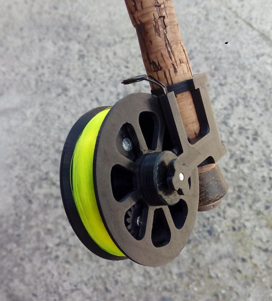
First fully functional reel with 50m of 16/100 line
As you can imagine, I was very excited and a bit anxious to test my reel for the firs time. But what's the value in all that if it is not functional ?
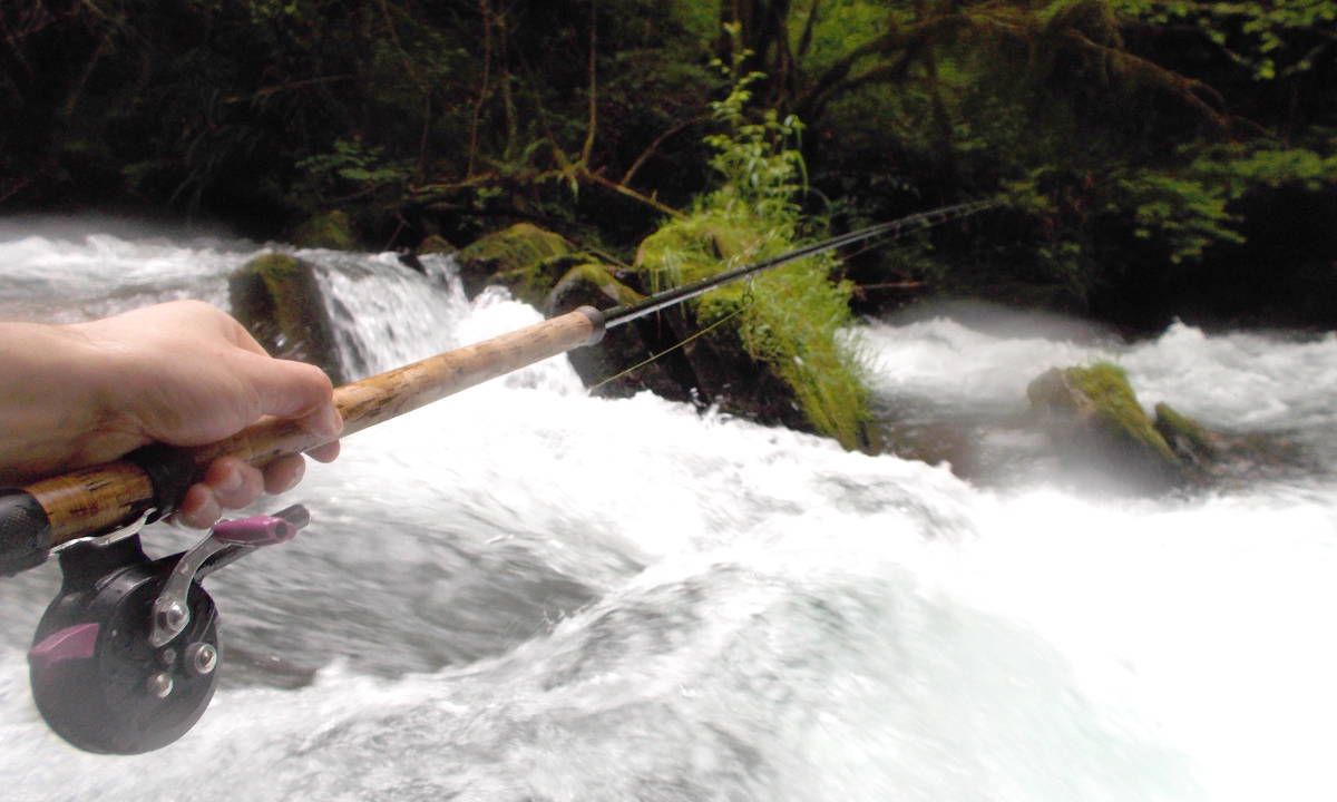
So I decided to go to one of my favourite spots to test the reel safely taking one of my good old reels with me as a backup. At that point, I was convinced that I would spend half of my fishing session struggling with the reel or taking notes of what was to be improved. Also, I had no idea how robust it would be when immersed or exposed to dirt.
Here are some picture of the session.


To my joy, it turned out that passed the first 15 minutes, I stopped thinking about the reel and got completely focused on the fish. That's about the best I could expect.
So it was a nice session of catch and release (I mostly release the fish since I'm fishing a lot).

After this, I decided to build another two reels to equip my other rod and keep a spare one which I did. I also tried different colours for the gears. This small batch it was the occasion to test the repeatability of the design which points at one difficulty at least : the alignment of the three planetary versus the ring and the sun. There is space for some misalignment since the planetary are made of two parts and this needs to be looked after. Also, post processing the parts is a long and boring job but it's very important to get the mechanism to work at its best to you need to clean excesses of PLA and grind printing scars away.
Now with half a season of experience, I am confident about the capacity of the reel to operate after accidental immersion. It always worked fine and I never lubricated it. I observed though the formation of some rust around one of the internal bearings which tends to show that it still affects it but probably in the longer term. I also found after a long time a quite annoying failure mode : that's when the line, rather than going the intended way, falls in between the reel and the mount. Ok, this does not happen very often and it needs to be seriously loose but it still happened and it's a bit tricky to get it back to where it needs to be.
Altogether, I like it and it's doing the job for me. It's not a top of the range reel and it's intended for a specific usage but for the price it's a pretty good value to me.

My three reels with some coloured gears
Here is a summary specification of the reel described :


/image%2F2071410%2F20170612%2Fob_949ce3_handles.jpg)
/image%2F2071410%2F20161024%2Fob_940c02_capture-du-2016-10-17-16-03-25.png)
/image%2F2071410%2F20160620%2Fob_ff763c_platonic-solids.jpg)
/image%2F2071410%2F20180303%2Fob_616e2f_manuel.jpg)